Building a Split Keyboard Part 3
In part 2 I covered the electrial design, and component selections I made for my keyboard project. In this post we’ll dive into the finishing, and assembly process.
Preparing the plates
The plates were some of the first parts I received, which was good as I could start wiring. I prepared the plates for assembly by spraying them with a clear coat. I didn’t want the brass plates to tarnish quickly. I learned from research, that to prevent this, brass needs to be sealed. I thought a few coats of spray varnish would seal them up. While it was effective for most of the plates there were a few spots that were missed, or got scratched that I didn’t notice until a few weeks later.
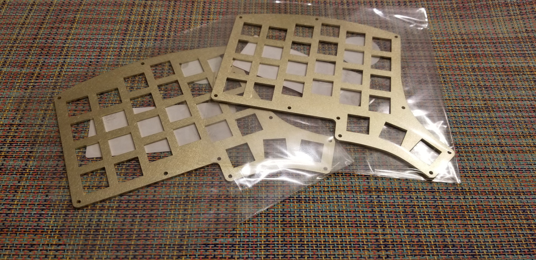
I obtained the plates from LaserBoost they were the most cost effective option for me. I attempted to contact 4 shops in my local city but never heard back from any of them. I have to assume my order was too small or that they were closed due to the pandemic. When I do my next keyboard, I’ll try local shops again.
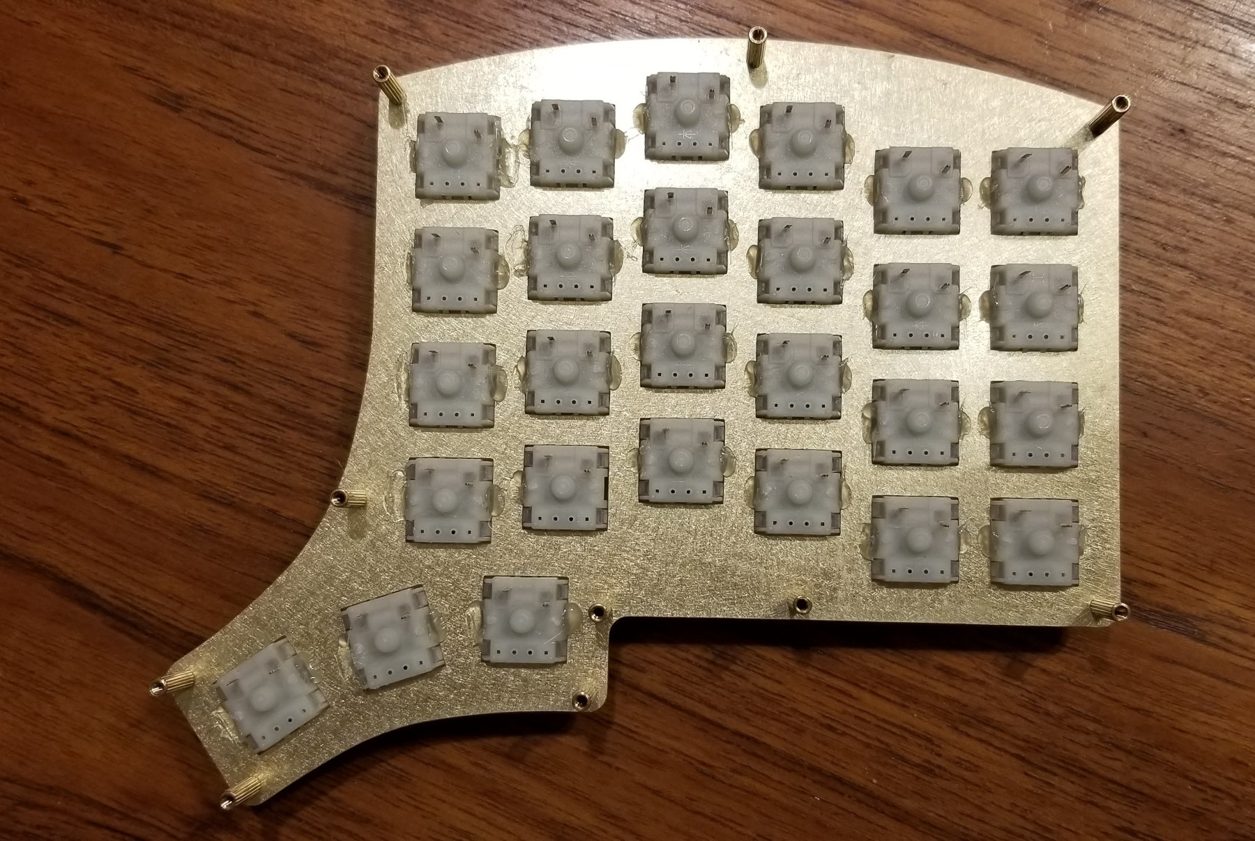
Switch installation
After the plates were finished, I installed the switches. I had hoped that the 1.5mm plates would provide a snug fit, and it was close. While the switches had some resistance to popping out they weren’t as tight as I wanted, a small dab of hot glue to each switch in the side cavities.
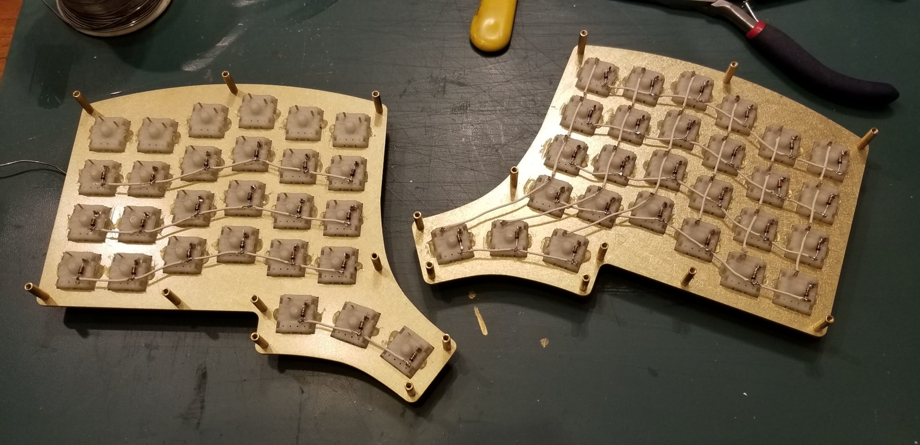
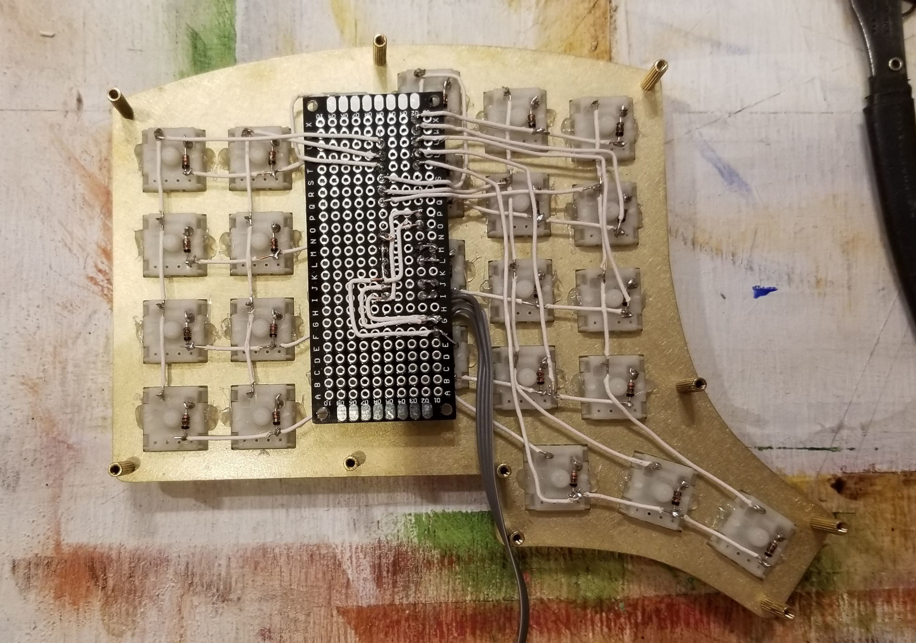
Wiring the matrix
Next up was wiring the matrix. Following the diode bending and soldering technique I ended up with matrixes that looked like:
Wiring the Microcontroller
With the matrixes wired, it was time to attach the microcontroller based on the wiring diagram I shared in part 2. Getting all the wires from the correct pins to the column and row wires was a slow fiddly process. I wanted the microcontroller to sit on top of the matrix to conserve vertical space. I also chose to locate the microcontroller in the middle of the matrix. This would give me room the ribbon cables I used to connect the USBC breakout boards with.
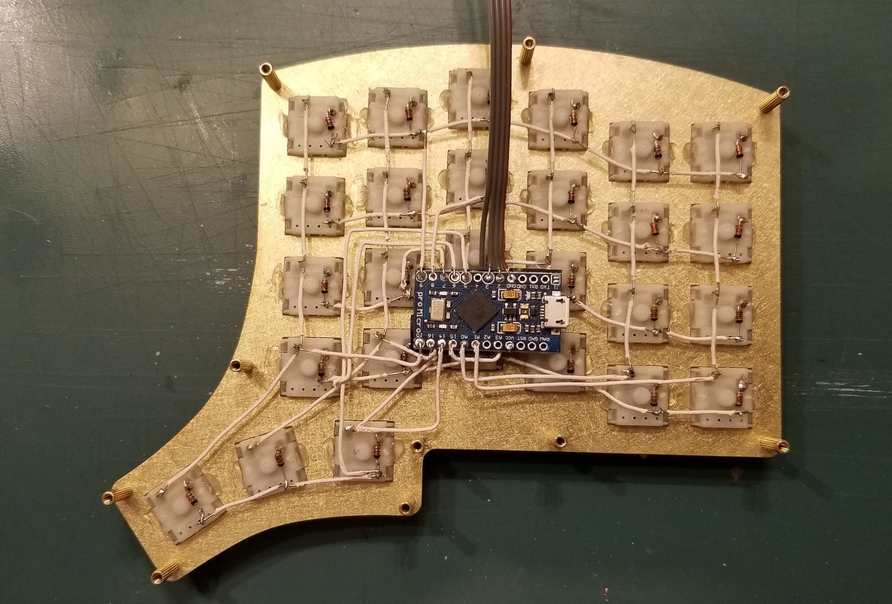
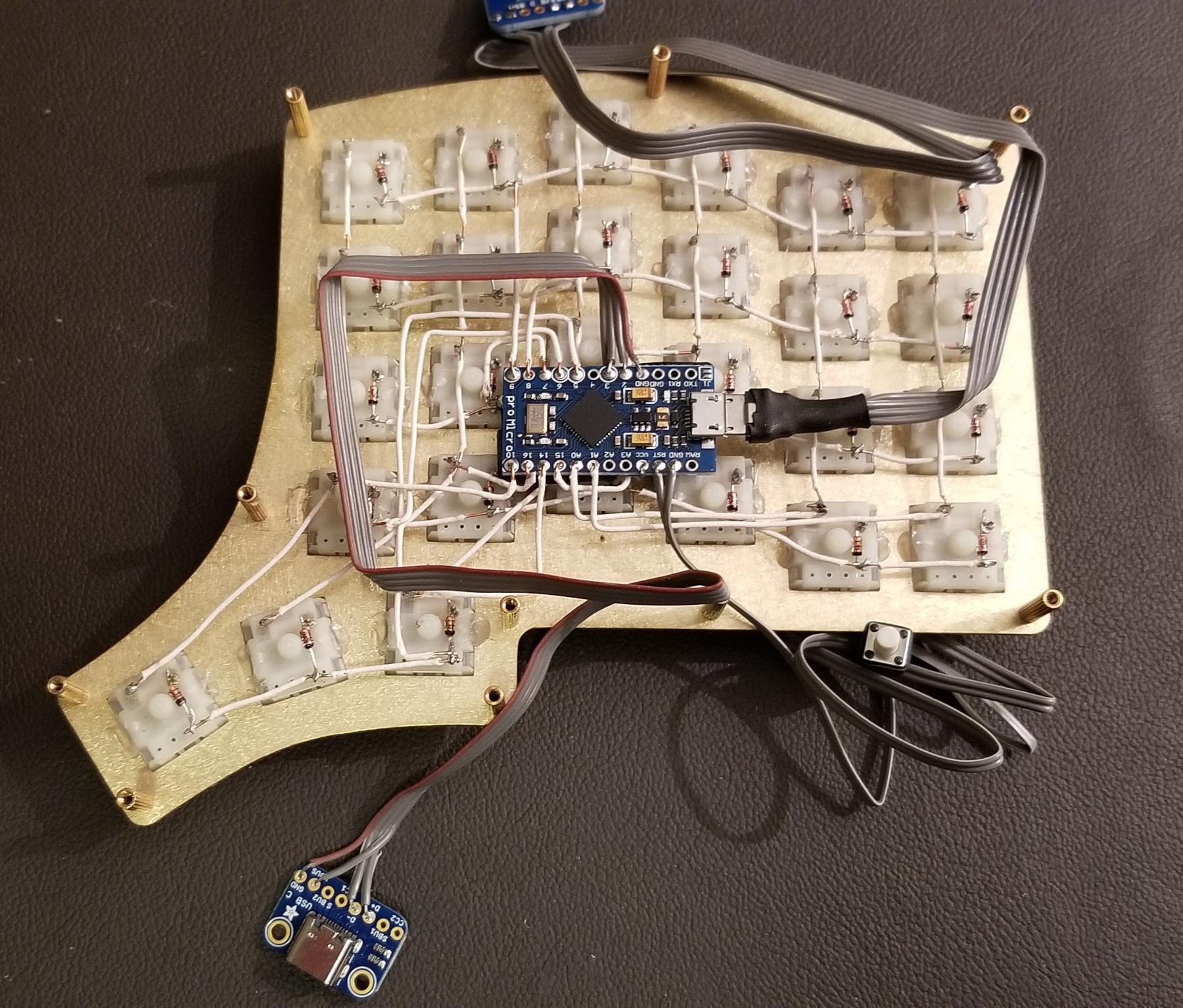
Now with the MCU in place, I could flash the firmware and test the left side on its own. From this I learned that my I2C timeout was too long, which was causing serious lag. I fixed this as, because using the left side on its own could be good for gaming.
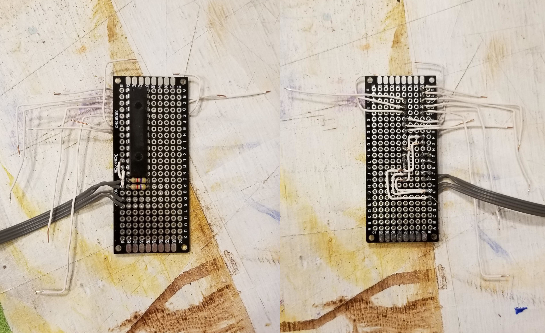
Wiring the IO expander
For the right side I had to mount the IO expander onto a protoboard. This was the most tedious part of the entire project. I spent a lot of time trying to figure out how to make the layout as compact as possible. I also struggled with the ‘best’ way to bridge pins and route wires. My final result ended up looking like:
Case milling and finishing
I’m extermely fortunate, and my brother has a 3-axis CNC machine that he uses for his custom knife business . This allowed me to get the case enclosure milled from a piece of smoked ash that my brother had in his workshop.
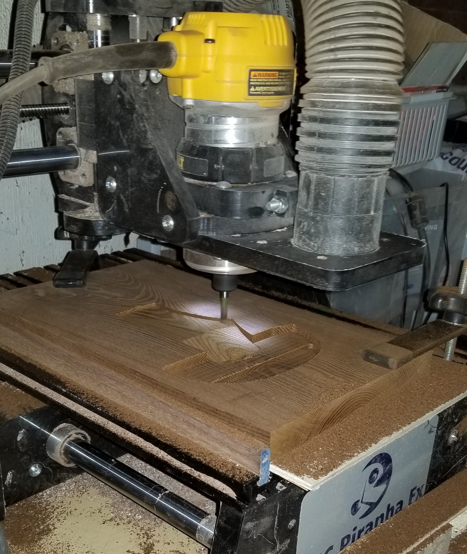
After milling process, the enclosures looked like:
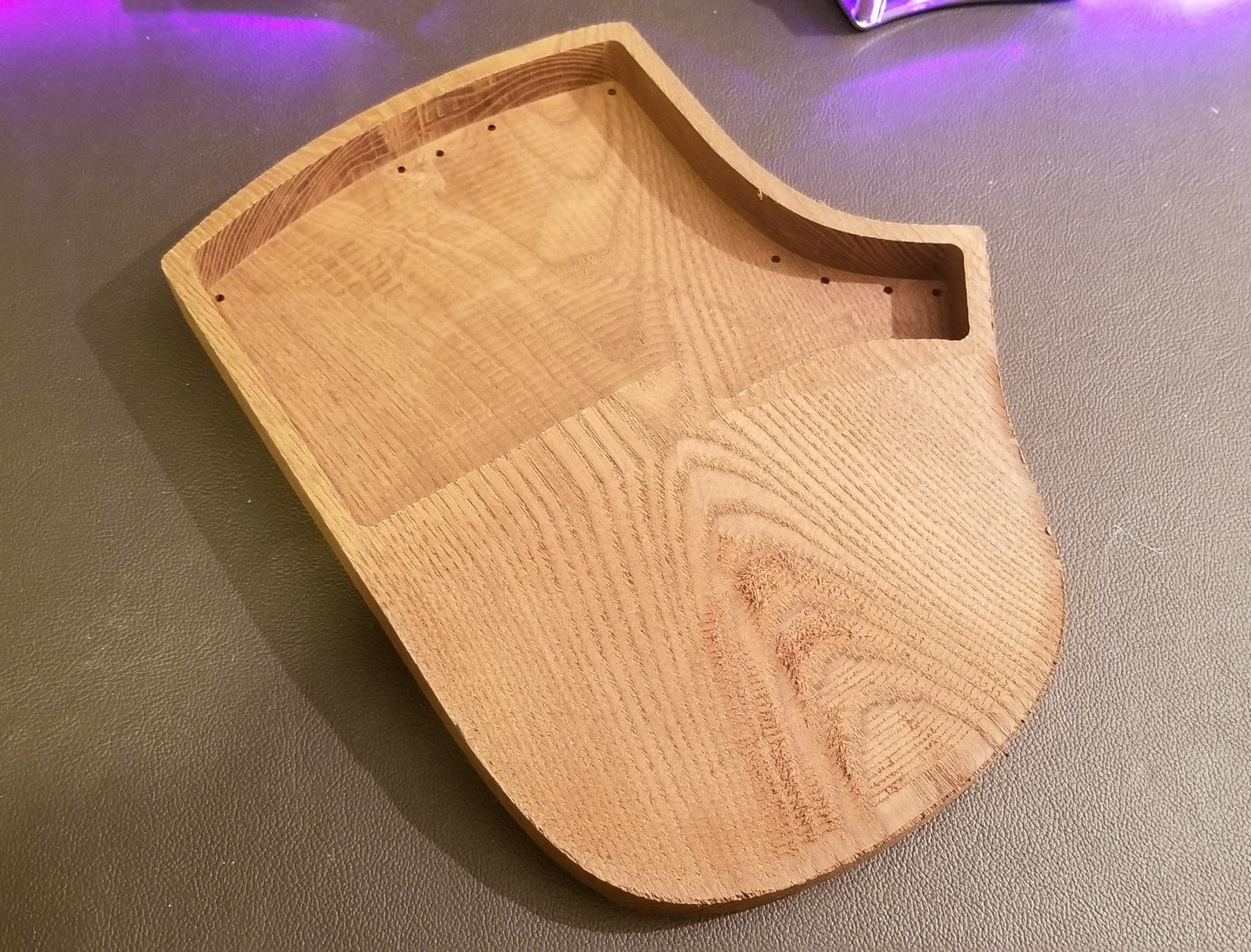
His CNC machine can’t drill the horizontal holes required for the USB ports. I planned to do these holes with a Dremel. Like all Dremel ideas I’ve had, this one ended up not as perfect as I had planned.
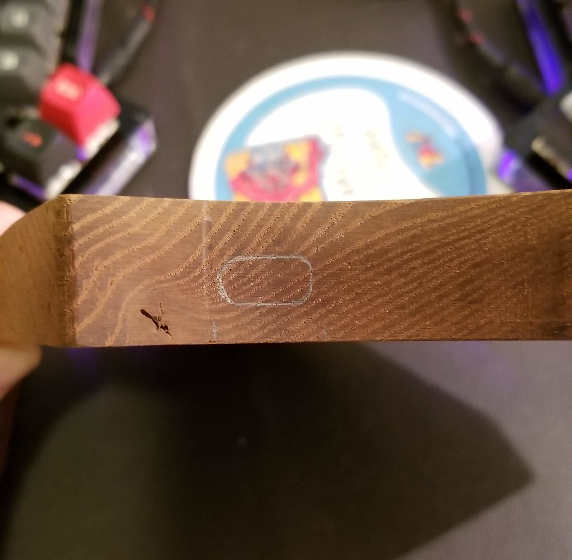
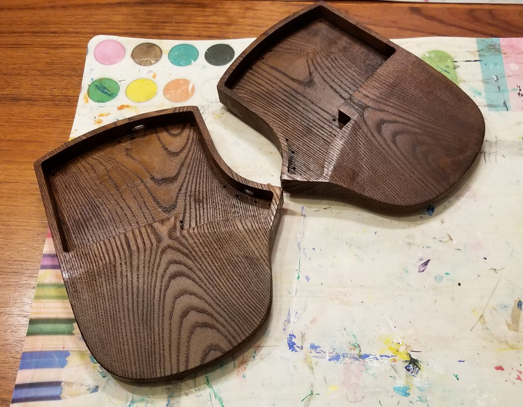
I won’t show the final outcome as I’m not overly pleased with it. I wanted a very smooth varnished finish. This took me a couple tries to get right as I didn’t sand the grain bumps out well enough the first time around.
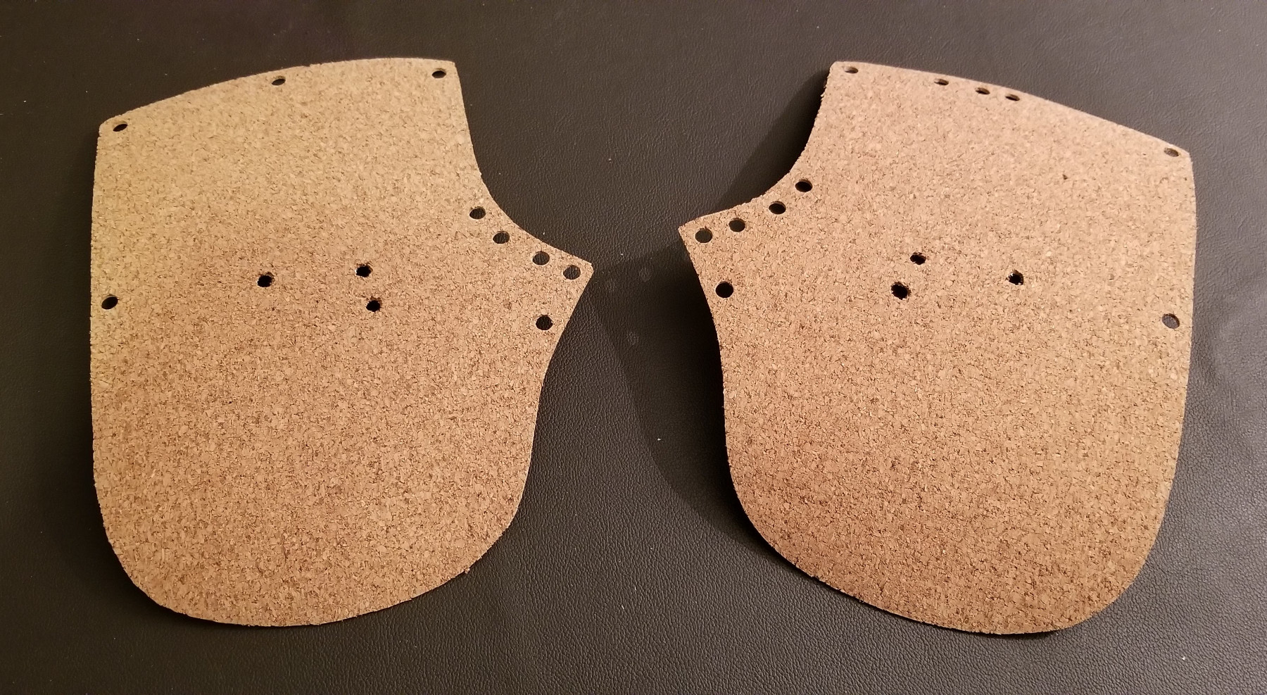
Mats
Because I was attaching the case and plate together with screws I wanted to have a non-slip surface on the bottom to prevent the screws from sliding and scratching the table surface. I chose to use self-adhesive cork as it was easy to obtain. I originally planned on getting mats lasercut, but with how hard it was to get plates cut, I cut the mats by hand with an x-acto knife.
Cables
I picked up a cable kit from Zap Cables they have a huge selection of casing options. I went with a simple black and white paracord to match the black and white key caps. I picked up a 36” cable for connecting to the host, and a 12” cable which I shortened to about 10” for the interconnect cable.
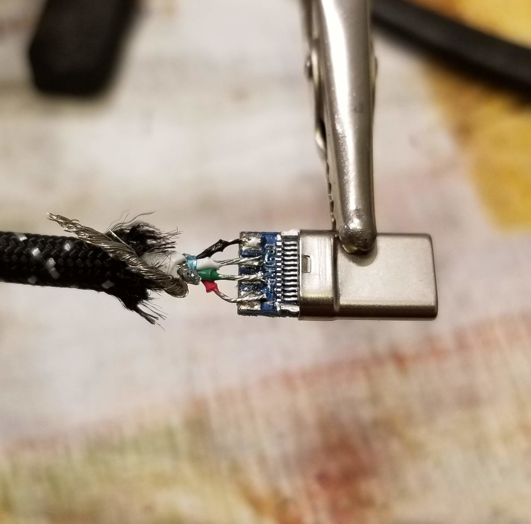
Like a total muppet, I wired the interconnect cable up wrong. I flipped the D+ and D- wires. Thankfully, nothing got fried and I was able to correct the problem. My pro-tip for cables is to test that they work before you snap the connectors closed and put heatshrink on them.
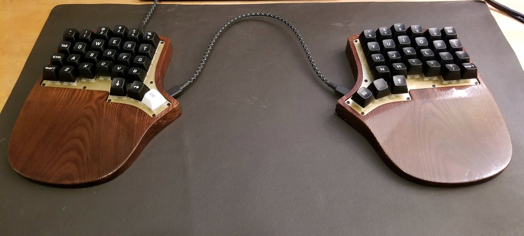
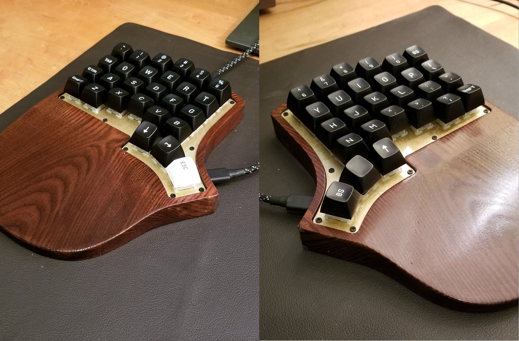
Final Assembly
With all the major components together, it was time to close this project up. Before I closed up the case, I hot glued the switch to the bottom of the case. Then I used simple black M2 screws and hex bolts to attach the USBC breakout boards. I used 12mm stand-offs to close the plate and case together. In hindsight these should have been 13mm but that is a lesson learned for next time. Then the keycaps went on and the cables went in. I had already flashed the firmware from earlier testing, so it was good to go. In the following weeks I continued to tweak the key mappings and am really happy with how it turned out.
This entire build cost me in approximately $350CAD. The breakdown of those costs are:
- Switches and lube $50
- Keycaps $104
- Wood – $0
- Plates – $95
- Cables – $33
- Screws & Standoffs – $9
- Electrical components $60
I ended up with a bunch of extra components as I bought extras in case of accidents, and some incorrect parts like the wrong IO expander, and RJ45 ports, and cables that I didn’t use. I also have 2 spare ProMicros for future builds.
Next Steps
With the a handwire build under my belt the next milestone will be designing a PCB and assembling that. This project will likely be a low profile switch build. I’ve used those switches before and would like to try them out.
Hi, I’m really in awe of your diy keyboard and it has inspired me to build my own layout too! I’m currently making a 40-key split layout and I’d like to know how you programmed your keyboard. Did you use qmk configurator or type your own code from scratch? And can you share that process too? Thanks!
Sivan on 1/22/22
Sivan: I used QMK for my board. Because I used an IO expander I had to write a custom matrix implementation. However, I was able to borrow and adapt my code from other keyboards in the QMK repo.
There wasn’t much of a process to that as QMK does most of the heavy lifting. Getting a keymap figured out was the most time intensive process of building firmware for this board.
mark story on 2/7/22